Evaluating Existing Load Paths Before Demolition
When transitioning a segmented residential layout into an open-concept living area, wall removal constitutes the single most consequential intervention in the remodel workflow.
Field measurements frequently reveal discrepancies between original subdivision blueprints and actual as-built conditions. Framing carpenters often redistributed roof trusses or floor joist bearings onto interior partition walls over decades of previous unpermitted modifications. Drafting an accurate as-built model demands verifying stud continuous load paths down to basement lally columns or foundation footings before calculating new beam profiles.
Critical Inspection Benchmarks for Interior Partitions
Differentiating non-bearing room dividers from structural shear or bearing assemblies requires physical inspection at attic and crawlspace levels:
- Perpendicular ceiling joist orientation resting on double top plates with continuous lap joints.
- Stacked vertical framing alignment directly over basement girders, steel I-beams, or intermediate support piers.
- Point loads originating from roof purlin struts or hip valley rafters transferring downward into intermediate partition heads.
Reconciling As-Built Delta with Proposed Beam Profiles
Once the load path is mapped, the comparative drawing set must clearly delineate the existing partition boundaries from the proposed flush or dropped LVL header. Using contrasting color fills—standardizing existing framing in charcoal tone and proposed steel or engineered lumber in bright cyan—prevents contractor misinterpretation during rough-in demolition.
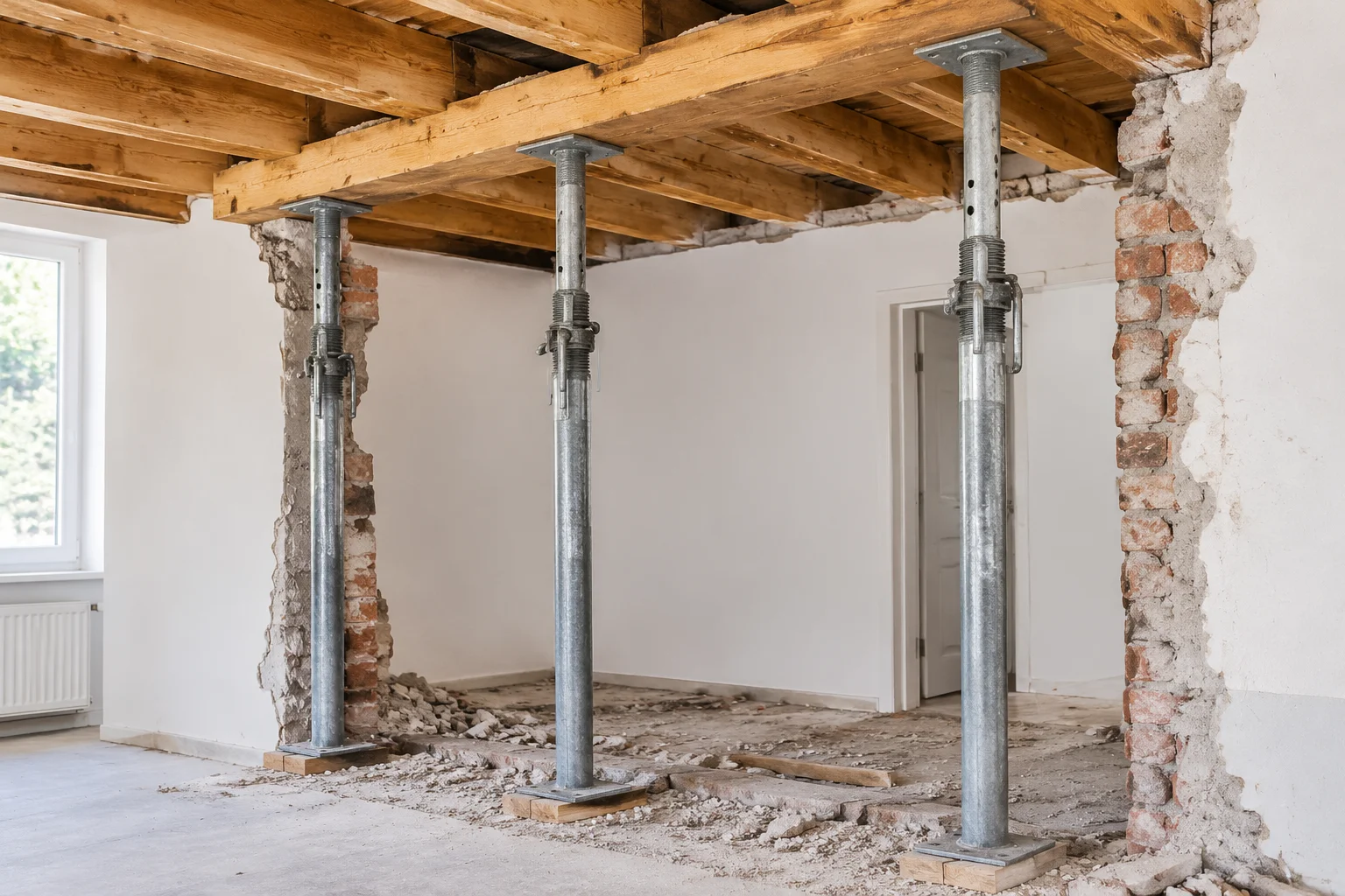
Temporary shoring must be engineered and visually noted on the demolition plan. Jacks positioned within thirty inches of the cutline transfer upper floor live loads safely while crews slot in pocket posts and post-cap hardware.
Deflection Control and Header Pocket Alignment
Calculating live-load deflection targets at L/360 or L/480 ensures that plaster ceilings in adjacent rooms remain free from shearing cracks when the temporary jacks are gradually decompressed.